P&id symbole
The ISA S5.
EdrawMax specializes in diagramming and visualizing. Just try it free now! A piping and instrumentation diagram is more complicated than a process flow diagram. Pumps and tanks come in a variety of designs and shapes. You have both abstract symbols and simulation images to choose from. Learn the basic knowledge about the piping and instrumentation diagrams. Pump is a mechanical device using suction or pressure to raise or move liquids, compress gases, or force air into inflatable objects such as tires.
P&id symbole
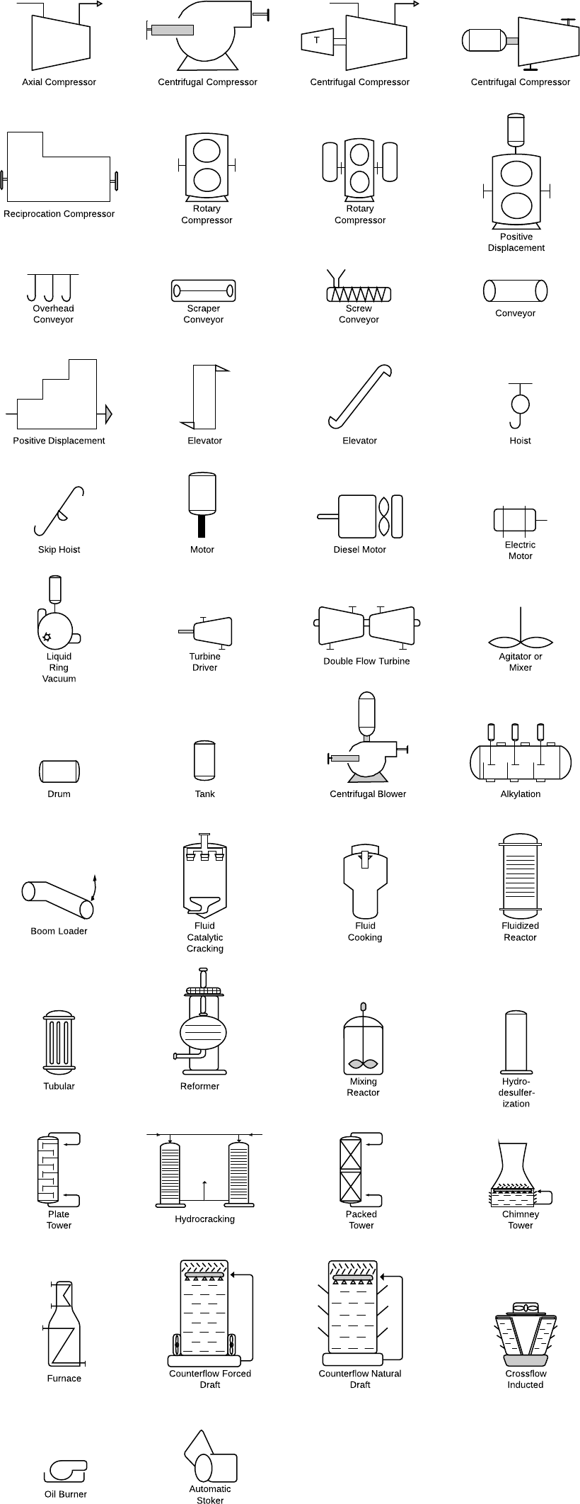
Piping and Instrumentation Diagrams are graphical representations of a process system. These are fundamental to every standardized engineering project. Piping and Instrumentation Diagrams detail the specific processes within a plant or industrial facility, including symbols that represent actuators, equipment, flow elements, instrumentation, piping fittings, valves. We recommend using the table of contents to navigate this comprehensive directory of common Piping and Instrumentation Diagram symbols. The symbols are organized in sections including equipment, fire and safety, flow elements, instrumentation, piping, valves, and more. Atmospheric tanks are containers for holding a variety of liquids at atmospheric pressure. There are various types as follows:. Compressors typically operate at a high pressure-to-volume ratio, while blowers operate at a low-pressure ratio. The most common driver used is the electric motor. Filters eliminate impurities from the passing fluid using physical, chemical, or biological processes to remove the contaminants.
Compressor 02 symbol. Contact me.
A flow diagram is a simple illustration that uses process symbols to describe the primary flow path through the production equipment. It provides a quick snapshot of the operating unit and includes all primary equipment and piping symbols that can be used to trace the flow of the well stream through the equipment. Secondary flows, complex control loops and instrumentation are not included. These PFDs are more helpful for visitor information and new employee training. However, there are many other abbreviations that you will see such as this more comprehensive industry list.
As this diagram covers many types of diagrams as the variety in industries is vast, many symbols are required. These diagrams provide a map for the engineering system's design which is helpful to problem identification and solving. The most popular instruments are actuators, equipment, flow elements, instrumentation, piping fittings, valves, and more. The major categories are piping, instrumentation, pumps, valves, vessels, heat exchangers, compressors, and equipment. There are multiple types of pipes that make them eligible for a separate category. It can be simple, multi-line, separators, connectors, end caps, flanges, reducers, and coupling. The list of piping symbols is as follows. Pumps are an essential part of the majority of industrial plants that need pumps, which can be used for suction, compression, moving fluid, and also for pressure control. There are many p and id symbols for pumps.
P&id symbole
Create powerful visuals to improve your ideas, projects, and processes. Work smarter to save time and solve problems. Helpful insights to get the most out of Lucidchart. Try Lucidchart. It's quick, easy, and completely free. The shapes in this legend are representative of the functional relationship between piping, instrumentation, and system equipment units. We've broken them down into seven main groups: equipment, piping, vessels, heat exchangers, pumps, instruments, and valves.
Mast chut ki chudai
This site uses Akismet to reduce spam. Pumps are an essential part of the majority of industrial plants that need pumps, which can be used for suction, compression, moving fluid, and also for pressure control. And what type of signal is being used. They are often manually controlled. Electrical Heating Vessel symbol. Compressor Vacuum Pump symbol. Installing a Clerestory Roof has to be planned beforehand, to accommodate the directions of sunlight, breeze, etc. Understanding pump symbols is essential since they provide crucial information on the functionalities of various pumps, their connections, and the direction of fluid flow within the system. Personal Cloud and Dropbox Integration. Posted by Janice. Weight Operated Dump Valves. Rotary Meter symbol.
These symbols can represent actuators, sensors, and controllers and may be apparent in most, if not all, system diagrams. The standard notation, varying from letters to figures, is important for engineers to understand because it a common language used for discussing plants in the industrial world. This section covers four main types of nomenclature.
Vessel symbols include those for tanks, cylinders, columns, bags, and others. T First Letter Measured variable RC Later letters Functions Loop number A Suffix Functional identification Loop identification Graphical representation of a temperature recorder controller of the A loop, suitable for control room mounting The following tables show: — Table 1 identifying the function of the instruments or devices — Table 2 the graphic identification of the valves — Table 3 the graphic identification of the actuators — Table 4 identifying the safety conditions of the valves and actuators At the end will also be reported the literal and graphic symbols of the power supplies and signals of the instrumentation. A heat exchanger transfers heat between different surfaces, fluids, mediums, or areas. Straightening Vane symbol. Turbine symbol. Searching for something else? Centrifugal Compressor 01 symbol. Normally Closed Ball Valve symbol. Tray Column symbol. These include ensuring consistency and understanding among team members, keeping abreast of industry standards, and staying updated with technological advancements.


In it something is. Clearly, I thank for the information.