Ph diagram 134a
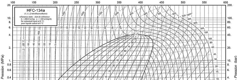
On the P-H diagram, pressure is indicated on the y-axis and enthalpy is indicated on the x-axis. The upside down U figure shown on the diagram designates the points at which the refrigerant changes phase.
Ra Pressure Enthalpy Chart. Scroll down to find download buttons for pressure enthalpy charts in either Metric or Imperial Units. Downloads as a PDF. You can download that software free of charge also using this link. Save my name, email, and website in this browser for the next time I comment.
Ph diagram 134a
.
Cooling takes place as heat flows from the hot refrigerant gas to the condenser cooling medium.
.
If you read my previous post about sealed system basics , you know that understanding the thermodynamic states of refrigerants saturated, subcooled, and superheated is essential to sealed system troubleshooting. In that post, I explained these states in terms of a simple pressure-temperature table. While that keeps things simple, it doesn't really give you a strong visual and mental model for how the refrigeration cycle works thermodynamically. That's why we're going to spend this whole post learning how to read a P-H diagram. It takes a bit more work than just reading a P-T table, but this diagram is where those values on the P-T table come from , so learning to read it will give you a deeper understanding of what's going on in the sealed system. Pretty overwhelming, right?
Ph diagram 134a
K Sat. I have enjoyed your youtube channel very much, thanks. I wander if you had any plans to publish the RA thermodynamic property tables? I was looking to run through the same calculations and compare the theoretical COP and cooling loads etc with the real experimental data. Thank you because of your complete description For full description I have a qaustion ,why do you start with kpa Pressure in step one of ra refrigeration? Save my name, email, and website in this browser for the next time I comment. The Engineering Mindset. Refrigerant Ra Properties. Specific heat capacity of materials. Density of Gases.
Premiumbull
Then the incoming temperature of the compressor, as determined by the leaving temperature of the evaporator, is used as the starting point of the compressor, as shown by point B' on the figure below. The equation to determine the net condenser effect is shown below. The enthalpy lines are the vertical lines. The condenser proceeds from right to left in the following three steps:. YouTube sets this cookie to store the video preferences of the user using embedded YouTube video. The uuid2 cookie is set by AppNexus and records information that helps in differentiating between devices and browsers. In this region there are vertical temperature lines, which increase as enthalpy is increased. Note on the graph below as the refrigerant moves from point D to point A, the refrigerant moves from the liquid phase of the graph to the vapor-liquid mixture region. Resistors Explained Mar 23, This cookie is set by the provider AdRoll to identify and show the visitor relevant ads by collecting user data from multiple websites.
The pressure-enthalpy diagram is the most common graphical tool for analysis and calculation of the heat and work transfer and performance of a refrigeration cycle. The change in pressure can be clearly illustrated on the p-h diagram.
The evaporator moves the refrigerant from point A partial liquid-vapor mixture to point B, a fully saturated vapor refrigerant. In this region there are vertical temperature lines, which increase as enthalpy is increased. The compressor is characterized by the refrigerant suction and discharge conditions. The input condition of the expansion device is determined by the condenser output conditions. The cookie is set by the GDPR Cookie Consent plugin to store whether or not the user has consented to the use of cookies. NID cookie, set by Google, is used for advertising purposes; to limit the number of times the user sees an ad, to mute unwanted ads, and to measure the effectiveness of ads. The cid cookie helps to identify unique visitors and understand their site behaviour at different times. The skeletal graph shown below shows the pressure-enthalpy lines. This equation multiples the refrigeration flow rate by the change in enthalpy between the discharge and suction conditions. You can download that software free of charge also using this link. Performance cookies are used to understand and analyze the key performance indexes of the website which helps in delivering a better user experience for the visitors.


I congratulate, this magnificent idea is necessary just by the way