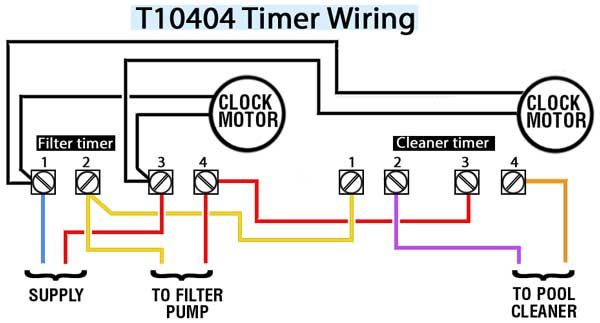
Intermatic timer wiring diagram
Forgot your Password? We welcome your comments and suggestions. All information is provided "AS IS.
How do you know if you have T Look at door label on inside of timer door. No label? Then read more Is power connected to double pole circuit breaker? Are there 5 screw terminals on timer? Are white clock wires on terminals 1 and 3? Is clock motor WG? If yes for all, then you have T
Intermatic timer wiring diagram
Follow along with the video below to see how to install our site as a web app on your home screen. Note: This feature currently requires accessing the site using the built-in Safari browser. Search Everywhere Threads This forum This thread. Search titles only. Search Advanced search…. Everywhere Threads This forum This thread. Search Advanced…. Log in Register. Install the app. Pool School.
It's critical that you answer Joed.
Search waterheatertimer. Search using. TM mechanism with fireman switch Buy: TM mechanism with fireman. Wiring for T Stranded wire will come loose and cause arcing. Use only solid copper wire. Do not use aluminum wire.
Running pool equipment 24 hours is usually unnecessary and expensive. Installing an Intermatic T timer is a great way to dramatically reduce run time and energy costs. The following steps will provide a guide on how to install the T timer. Note, timers vary with supply voltage. A T timer is used for V supply voltage. If you are using V supply voltage, you will need a T timer. The installation steps are the same for either. Toggle navigation Menu Cart My Account.
Intermatic timer wiring diagram
Hide thumbs. Quick Links. Enlarged version. Troubleshooting Guide Observed Problem. The time of day or timer settings have not.
Sheena parveen san diego
This is the box with the red wire that had come loose marked S1 attached to where I think it belongs. Cannot use 2 separate GFCI breakers to supply volt. Turn the manual timer switch off. Step 28 Locate the "Off" tripper. The replacement is part number TM. One knockout will lead to the breaker panel and the other will lead to the pool equipment. Intermatic timer replacement and wiring fix. Use wire stripper and not knife. Although they both will functionally work, switching the hot is the correct way. One cable will go to teminal 2 and the other to terminal 4. Local electrical codes for commercial wiring will determine which voltages can be used. Is it possible to wire an additional outlet for ?
.
Otherwise, the motor would not work as all electric loads need a supply of voltage and a return. The evidence and rating tell us that maximum for the timer Step 30 Turn on the the power at the breaker panel. Thank You Read More. You can wire the ST01 in a 4-Way setup. The motor should be running regardless of the load switch positions. Loose Porcelain tile on second floor bathroom. I used them this afternoon, and we're back in business. When T timer turns off, the pump resumes high-low operation based on when the T timer is in high or low. Note: This feature currently requires accessing the site using the built-in Safari browser. AVS Forum.


What charming answer