Dd15 rocker shaft torque specs
Views 77 Downloads 2 File size KB. The top thread section of the nu. All information subject to change without notice. If removed, install the air compressor gear to the air compressor shaft and secure with nut.
Download Now Download to read offline. Recommended Hyundai D4DD engine manual. Hyundai D4DD engine manual Viktor. Motor perkins-manhual de taller. Motor perkins-manhual de taller Oscar Huamani Romero. El freno de motor.
Dd15 rocker shaft torque specs
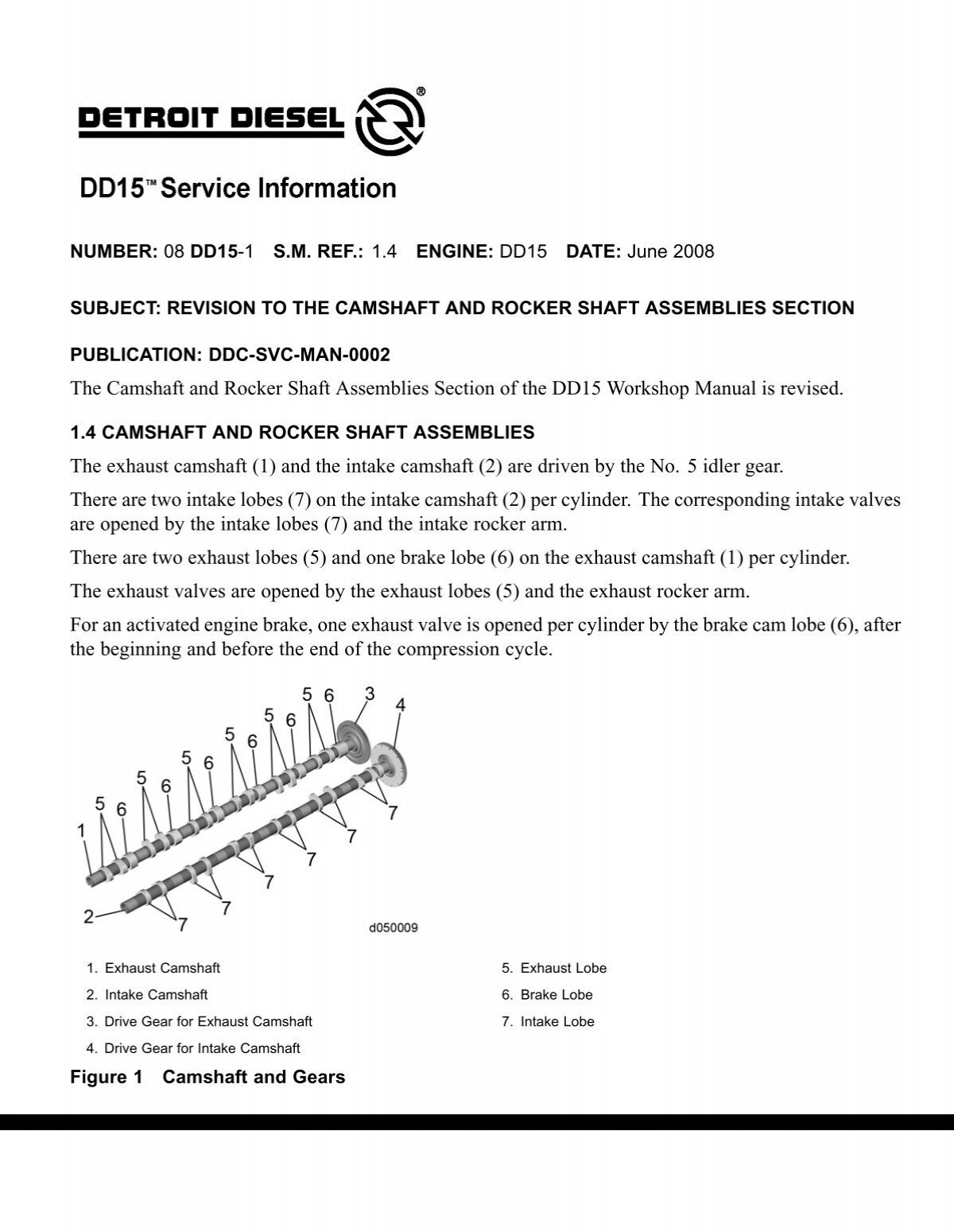
There are two intake lobes 7 on the intake camshaft 2 per cylinder. The corresponding intake valves are opened by the intake lobes 7 and the intake rocker arm. There are two exhaust lobes 5 and one brake lobe 6 on the exhaust camshaft 1 per cylinder. The exhaust valves are opened by the exhaust lobes 5 and the exhaust rocker arm. For an activated engine brake, one exhaust valve is opened per cylinder by the brake cam lobe 6 , after the beginning and before the end of the compression cycle. Exhaust Camshaft 5. Exhaust Lobe 2. Intake Camshaft 6. Brake Lobe 3. Drive Gear for Exhaust Camshaft 7.
Only the two bottom bolts on More information. Remove throttle linkage.
Share your interactive ePaper on all platforms and on your website with our embed function. See Figure 4. See Figure 5. Refer to section 2. Refer to section
The rocker cover 2 is made of an aluminum or plastic material and uses an elastomer seal 1 which completely encloses the valve operating mechanism including the overhead camshafts, brake assemblies and the injector harness. Loosen the bolts 1 or stud bolts 2 if equipped and isolators 3 ; remove rocker cover. Mark the location of the stud bolts. The stud bolts must be replaced in their original location during installation. Blow dry with compressed air. Check the rocker cover, breather passage and seal for damage. Replace as necessary. Inspect the bolts.
Dd15 rocker shaft torque specs
There are two intake lobes 7 on the intake camshaft 2 per cylinder. The corresponding intake valves are opened by the intake lobes 7 and the intake rocker arm. There are two exhaust lobes 5 and one brake lobe 6 on the exhaust camshaft 1 per cylinder.
Shaveshop
If the O-ring or the coolant line retainers are missing or removed, replace the coolant line. More documents Recommendations Info. Your name. Jump to Page. Install as follows: 1. AND NO. Terms of service. Figure 9 Tool W Using tool W , install the assembled intake rocker arm assembly to the camshaft cap and secure with seven clamping blocks and bolts. Viewers also liked Tablas de torque. Please read this instruction booklet carefully before beginning. Install the air lines to and from the air compressor. You can have confidence knowing that your EPA engine is backed by the total coverage of Cummins. Figure 7 Marking Groove 1.
Share your interactive ePaper on all platforms and on your website with our embed function. See Figure 4.
Torque the bolts to N m lb ft 90 degrees. Exhaust Rocker Arm Shaft Assembly 6. Install the air lines to and from the air compressor. Intake Lobe 4. See Figures 8 and Install the injectors and harness. Install the exhaust and intake camshaft gear assemblies onto camshaft housing caps. See Figure Torque fourteen mm M10 camshaft cap bolts andsevenmmm10boltsto20n m 15 lb ft and then torque to N m lb ft using torque sequence shown in Figure 6. Install the 28 bolts to camshaft caps; finger tighten the bolts. Install as follows: 1. What is Scribd? Rear Timing Tool 2.


You are not right. I am assured. Let's discuss. Write to me in PM.