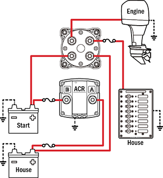
Boat battery switch wiring diagram
The most obvious and most common is simply to use it to turn off your battery when in storage so that your battery does not drain as quickly and is ready to go when you are. Like all Perko products, boat battery switch wiring diagram, these time-proven switches are made in the USA.
In a boat, electricity is stored in one or more batteries. They can hold an enormous amount of energy, capable of pushing hundreds, or even a thousand amps more than your entire house uses … so care must be taken, and proper circuit protection should not be ignored. Greatly generalizing the topic here, but you usually run into two types of batteries in the size of boat we deal with:. Batteries have positive and negative. For current to flow which does the work a complete circuit must be made from positive back to the negative. A normal battery might have AH amp hours of capacity.
Boat battery switch wiring diagram
Forums New posts Search forums. Media New media New comments Search media. Resources Owners Manuals test3. Showcase New items Latest reviews. Log in. What's new. Search Everywhere Threads This forum This thread. Search first posts only. Search titles only. Word Count:. Search Advanced search…. Everywhere Threads This forum This thread. Search Advanced…. New posts.
The positives of course must be installed on the correct gang associated with the respective switch for that load. Batteries are at the heart of the electrical systems found on any boat or vehicle. Apr 4, 2, 12, Springfield Ohio Ownership
Batteries are at the heart of the electrical systems found on any boat or vehicle. Proper battery management, including switching and charging, is essential for safe and reliable operation. For more detailed wiring guidelines please consult a qualified marine electrician or one of the many books available on the subject. The diagrams below are intended for reference only. Consult an ABYC certified marine electrical professional for system design and circuit protection. Found this article helpful? Get the latest when you sign up for our newsletter!
Batteries are at the heart of the electrical systems found on any boat or vehicle. Proper battery management, including switching and charging, is essential for safe and reliable operation. For more detailed wiring guidelines please consult a qualified marine electrician or one of the many books available on the subject. The diagrams below are intended for reference only. Consult an ABYC certified marine electrical professional for system design and circuit protection. Found this article helpful? Get the latest when you sign up for our newsletter! Follow BlueSeaSystems.
Boat battery switch wiring diagram
Do you have some experience with boat electrical systems, but the wiring process seems daunting? Look no further! In this comprehensive boat battery wiring diagram guide, I will take you through the process of connecting your marine batteries in a hassle-free manner. From understanding the basics of boat battery wiring to following a step-by-step guide, I will cover everything you need to know to ensure a safe and efficient electrical system on your boat. Knowing the marine battery wiring diagram and boat electrical system diagram will help you grasp the fundamentals of boat battery wiring and make the process easier.
Jerry o connell net worth
Your donations are all we have to fund this web site. There are however some important nuances to the Level 3 upgrade. But a BOTH marine battery switch also allows you to parallel both batteries. If you take a look at where your DC loads are connected, this just happens to be the same exact place as the factory wired alternator, the c-post. This is what it looks like.. For customers with this set up I simply leave a copy of all the scenarios of switch use on-board. We have an in depth article here on how to wire a bilge pump … check that out as well for more details. Even a fraction of a second disconnect is enough to cause an alternator load-dump. The addition of the ACR eliminates the need to move the switch for charge directing. Word Count:. The voltage transient from a battery switch disconnect often destroys the alternator diodes and it can also damage or murder your sensitive DC electronics. High conductivity studs are long enough to handle more than 1 cable and strong enough for torque needed for secure connections. You have cookies disabled.
The most obvious and most common is simply to use it to turn off your battery when in storage so that your battery does not drain as quickly and is ready to go when you are.
Much appreciated. Search Advanced search…. The diagrams below are intended for reference only. DanSmith Jul 21, General Discussion. TIP: use the tabs to view and hide notes. To grasp this we need to understand that a house bank is typically much, much larger than a start bank. As you now know, when you open the battery switch, while charging, there is a high likelihood the diodes in the alternator will be blown. A normal battery might be able to push A or more current A normal battery might have AH amp hours of capacity. Label them carefully, Blue Sea Systems sells the perfect labels. In nearly all cases your boat wiring system should have a marine-grade main battery disconnect switch.


0 thoughts on “Boat battery switch wiring diagram”