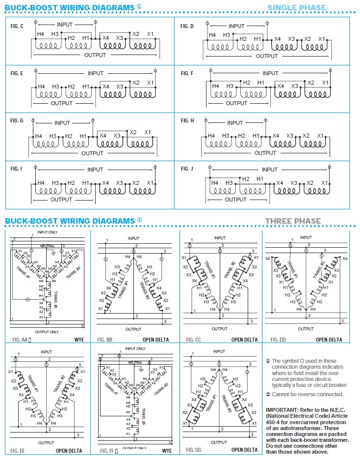
Acme transformer wiring diagrams
Forums New posts Search forums. What's new New posts.
To report an issue with this product or seller, click here. Customer Reviews, including Product Star Ratings help customers to learn more about the product and decide whether it is the right product for them. Instead, our system considers things like how recent a review is and if the reviewer bought the item on Amazon. It also analyzed reviews to verify trustworthiness. Report an issue with this product or seller.
Acme transformer wiring diagrams
View Full Version : Wiring isolation transformers. I am wondering the proper way to wire the isolation transformer green ground wire on the output side. The instructions have a number of different wiring diagrams. Can you guys let me know what you have done. I'm adding isolation transformers this winter as part of a total re-do of the electrical on my 41 TC. My personal participation in the project is mostly limited to scratching the check to the contractor. I do have a pdf diagram that describes the wiring. Its too large to upload here. If you PM your e-mail address I'll send it. It may be of some help to you. Their diagrams look like they may be from ABYC anyway. It's my understanding that a Galvanic Isolator prevents electrocution in the event that AC current escapes from the AC wiring on board i.
Back to top. New User?
Industrial Control Transformers provide a low and safe control voltage for the operation of electromagnetic devices, such as motor starters, contactors, solenoids and timers or other loads requiring above average voltage regulation when actuated. The windings and internal terminations are sealed in epoxy encapsulant and encased in a durable thermoplastic end cap, protecting them from potentially damaging moisture, dirt and other ambient contaminants. Our models are designed especially to accommodate the momentary current inrush caused when electromagnetic components are energized Voltage regulation exceeds standards recommended by NEMA. Secondary circuit voltage drop between no-load and momentary overload remains exceptionally low. This excellent secondary circuit voltage regulation assures reliable operation of electromagnetic components and may permit the use of a smaller and less expensive transformer. They are especially designed to accommodate the momentary current inrush caused when electromagnetic components are energized without sacrificing secondary voltage stability beyond practical limits.
When it comes to handling the power that runs industrial machines, few components can match the performance of an Acme Transformer T 2 3s. With its sophisticated design, this transformer has become a favorite of engineers around the world for its reliability and efficiency. However, for those who work with these powerful machines, understanding how to install and operate them can be a daunting task. Fortunately, with the help of wiring diagrams for Acme Transformers, even novice engineers can gain the knowledge and confidence needed to get the job done safely and effectively. This document contains all the information required to configure and operate the transformer, such as the connection types, wiring diagrams, and safety instructions.
Acme transformer wiring diagrams
From providing power to control panels to powering variable speed drives, V to V transformer wiring diagrams are an invaluable tool for electricians and other professionals. But how do you make sense of it all? This guide will help you get to grips with what V to V transformer wiring diagrams look like, how they function, and the most common applications. In simple terms, a V to V transformer wiring diagram allows you to connect two different voltages — V and V. By using the transformer, you can turn the higher voltage into a lower one.
Sifting litter boxes for cats
I have 3 phase in the panel so it is not a problem to have 2 feeds. Community Member List. Measure the coil resistance again. Did I throw gas on the fire or clear things up? Thanks again. I have an Acme industrial control transformer that I need help wiring. From your replies I am understanding that the boat side green ground on both transformers should be attached to the boat's grounding system. Get to Know Us. Resistance breaker to breaker. Also, do I pull the nuetral for the v circuit from the X on the bottom of the transformer? The main situation where marine electronics are special are in the engine rooms of gas powered boats. Where are they going? Location Los Angeles CA.
.
If they were on different phases it would be v. See all details. Log in. Forgot your Password? New Posts. Find all posts by Nashkat1. New posts. I am wondering the proper way to wire the isolation transformer green ground wire on the output side. Location NE Nebraska. Width Inches Cm. Put a heavy load on it. Related Articles.


It is possible to fill a blank?